Unit 5.1 Von Neumann Architecture
这节课的标题是冯诺依曼结构,实际上讲到了 3 个概念:数据总线(data bus)、地址总线(address bus)和控制总线(control bus)。这些总线就是计算机内部信息的公路,比特流在这些总线上流动,不同功能的比特流在不同的总线上流动。计算机的硬件设备,如内存、CPU等都连接在这些总线上,时不时的读入信息和输出信息。
Unit 5.2 The Fetch-Execute Cycle
这节课主要在讲解提取-执行周期(Fetch-Execute Cycle)的大致过程。按照前面的思路,程序的数据和控制指令都保存在一块内存芯片中,那 CPU 是如何知道什么时候该执行那条指令,如何去分辨控制指令和数据呢?
实际上,CPU 有一个叫做 Program Counter 的程序寄存器来专门记录内存中保存指令的地址,数据地址和指令地址(Program Counter)中保存比特的一同流入 Multiplexor 中,而这个多路复用器用一位控制位来区分现在是提取(Fetch)周期还是执行(Execute)周期。如果是提取模式,那么就读取指令地址,将具体的指令加载到 CPU 中;如果是执行周期,就读取数据地址,将具体的数据加载到 CPU 中用于执行。
Unit 5.3 Central Processing Unit
这节课的主要内容是 CPU 的内部结构、功能和对应的实现原理,讲的不是很深入。
CPU 实际上就是 ALU 和其他寄存器的组合体,与计算相关的功能是由 ALU 实现的,过程控制是由 ALU 和其他寄存器组合完成的。
老师用上周讲的 A 指令和 C 指令举例,说明了 CPU 是如何识别这些指令,如何实现这些指令的功能,这里就不具体展开了。
Unit 5.4 The Hack Computer
这节课主要在讲 Hack Computer 的结构:一块 CPU、一个 ROM32K 的外存、一块内存,再加键盘和屏幕两个 I/O 设备。
接着老师又分开讲解了每部分硬件的构成原理,不过讲的不是很深入,与前面提到的差不多,毕竟这一周的任务就是做这些东西。
Unit 5.5 Project Overview
这周主要实现 3 个硬件设备,而这些设备就是上一周用到的设备。
Memory
第一个实现的设备是 Memory,实现过程真是一言难尽,明明是相对容易的问题,却想了很久,最后才意识到是自己有些基础概念(或者说默认规则)没理解清楚,导致做不出来,查资料纠正过来后,就迎刃而解了。
但话说回来,能这样一步步做到第五周也是没谁了😅...不多说了,进入正题。
Memory 的实现相对比较简单,参考资料已经给了很详细的提示——参考第三周构造内存芯片的思路完成。
按照提示的思路,完成 Memory 需要使用 RAM16K、Screen 和 Keyboard 这三个主要芯片,然后再加上其他若干芯片。此时,已知的内容是 Memory 的地址范围在$[0, 24576]$,并且分别对应着内存、显示器和键盘的地址范围,即:1
2
30x0000 - 0x3FFFF -> 0000 .... 0000 - 0111 .... 1111 -> Ram
0x4000 - 0x5FFFF -> 0010 .... 0000 - 0101 .... 1111 -> Screen
0x6000 -> 1100 .... 0000 -> Keyboard
结合实现 RAM16K 的思路,实现 Memory 也需要使用一个 DMux4Way 将输入的地址区分开,然后将特定的管脚连接到特定的芯片上即可,最后再用 Mux4Way16 输出即可,整体思路还算是比较简单的。
因为已经知道 RAM16K 是 14 位寻址的,Screen 是 13 位寻址的,Keyboard 就一个地址,而 Memory 的 address 是 15 位的,所以可以很自然的想到用 address 的前两位来作为 DMux4Way 的 sel bits,这样就可以区分出地址了。
但是,在选择管脚作为 sel bits 和连接管脚的时候,我没有搞清楚在 hdl 语言中比特流到底是怎么流动的,导致我无论怎么操作管脚都是错误的...(虽然按照错误思路编写好的 hdl 能跑完和内存相关的部分脚本)
具体而言,以一条 A 指令为例:1
2
3
4
5
6
7
8
9
10
11
12
13
14 指令 对应的比特流 流入机器的顺序(与人正好相反)
@3001 -> 000101110111001 -> 100111011101000
之前理解的比特流在 hdl 中的顺序
v[0] v[1] v[2] v[3] ... v[13] v[14]
0 0 0 1 ... 0 1
实际比特流在 hdl 中的顺序
v[0] v[1] v[2] v[3] ... v[13] v[14]
1 0 0 1 ... 0 0
所以,在 hdl 中,选取头两位作为 sel bits,就应该选取 v[13] 和 v[14] 而不是 v[0] 和 v[1],
同时可以发现,实际顺序中的 0 - 14 也确实代表着进入到计算机内的比特流顺序,也说明这样表示是科学的。
PS:这里其实可以深入扩展一下 MSB 和 LSB 的概念。
最后,贴出正确的实现代码:1
2
3
4
5
6
7
8
9
10
11
12
13
14
15
16
17
18
19
20
21
22
23
24
25
26
27
28
29
30
31
32
33
34
35
36
37
38
39
40
41
42
43
44
45
46
47// This file is part of www.nand2tetris.org
// and the book "The Elements of Computing Systems"
// by Nisan and Schocken, MIT Press.
// File name: projects/05/Memory.hdl
/**
* The complete address space of the Hack computer's memory,
* including RAM and memory-mapped I/O.
* The chip facilitates read and write operations, as follows:
* Read: out(t) = Memory[address(t)](t)
* Write: if load(t-1) then Memory[address(t-1)](t) = in(t-1)
* In words: the chip always outputs the value stored at the memory
* location specified by address. If load==1, the in value is loaded
* into the memory location specified by address. This value becomes
* available through the out output from the next time step onward.
* Address space rules:
* Only the upper 16K+8K+1 words of the Memory chip are used.
* Access to address>0x6000 is invalid. Access to any address in
* the range 0x4000-0x5FFF results in accessing the screen memory
* map. Access to address 0x6000 results in accessing the keyboard
* memory map. The behavior in these addresses is described in the
* Screen and Keyboard chip specifications given in the book.
*/
/*
0x0000 - 0x3FFFF -> 0000 .... 0000 - 0111 .... 1111 -> Ram
0x4000 - 0x5FFFF -> 0010 .... 0000 - 0101 .... 1111 -> Screen
0x6000           -> 1100 .... 0000 -> Keyboard
*/
CHIP Memory {
IN in[16], load, address[15];
OUT out[16];
PARTS:
// Put your code here:
DMux4Way(in=load, sel=address[13..14], a=load0, b=load1, c=loadsrc, d=loadkb);
Or(a=load0, b=load1, out=loadram);
RAM16K(in=in, load=loadram, address=address[0..13], out=uram);
Screen(in=in, load=loadsrc, address=address[0..12], out=usrc);
Keyboard(out=ukb);
Mux4Way16(a=uram, b=uram, c=usrc, d=ukb, sel=address[13..14], out=out);
}
另外,还有一点,Memory 的测试脚本在执行到测试 Keyboard 的时候,需要在软件上切换成键盘输入,具体的操作方法(Stackoverflow 论坛上的方法):
To anyone facing the same problem… on the Hardware Simulator user interface, right above where you see the script executing the tests, there are three drop down boxes. The one furthest to the right which is labeled “View” is probably currently set to “Script.” Click the drop down and select “Screen,” and you will see an interface that has a keyboard icon. Click it and then hit the corresponding key to complete the test.
CPU
第二个实现的是 CPU,花了我半个月的时间,总算是大致理解了设计原理,而且还是参考别人的做法...
想要完整的设计出 CPU,首先必须要搞明白老师课上给的设计图:
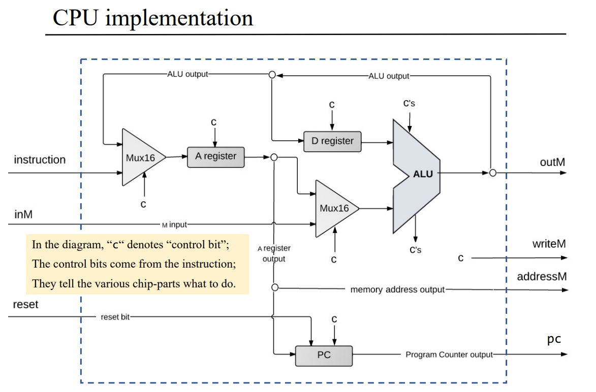
这张图清楚的标出了 bits 在 Hack-CPU 中的流动,并指出了在特定 control bit 位置时所使用的芯片,所以需要我们做的事情就是搞清楚这些 control bit 是什么和并合理使用它们得到想要的输出。
从图中可以看到,整个 CPU 一共有 4 个输出,分别是:outM、writeM、addressM 和 pc,还有 3 个输入,分别是:instruction、inM 和 reset,这些名词的含义可以直接从hdl文件中得到:1
2
3
4
5
6
7
8
9inM[16], // M value input (M = contents of RAM[A])
instruction[16], // Instruction for execution
reset; // Signals whether to re-start the current
// program (reset==1) or continue executing
// the current program (reset==0).
outM[16], // M value output
writeM, // Write to M?
addressM[15], // Address in data memory (of M)
pc[15]; // address of next instruction
按照课程中老师讲解的思路,我们可以先实现与 ALU 相关的内容:
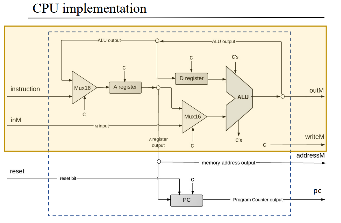
为了方便表示和使用,提前一次性将 C 指令的各个 bit 全部提取出来:1
2
3
4
5
6
7
8
9
10
11
12
13
14
15
16// C-ins
And(a=instruction[15], b=instruction[12], out=ca); // a
And(a=instruction[15], b=instruction[11], out=c1); // c1
And(a=instruction[15], b=instruction[10], out=c2); // c2
And(a=instruction[15], b=instruction[9], out=c3); // c3
And(a=instruction[15], b=instruction[8], out=c4); // c4
And(a=instruction[15], b=instruction[7], out=c5); // c5
And(a=instruction[15], b=instruction[6], out=c6); // c6
And(a=instruction[15], b=instruction[5], out=d1); // d1
And(a=instruction[15], b=instruction[4], out=d2); // d2
And(a=instruction[15], b=instruction[3], out=d3); // d3
And(a=instruction[15], b=instruction[2], out=j1); // j1
And(a=instruction[15], b=instruction[1], out=j2); // j2
And(a=instruction[15], b=instruction[0], out=j3); // j3
ARegister and inM
这里我们按照 instruction 和 inM 从左至右的方向进行实现,首先实现的是与 ARegister 相关的内容。
按照图示,指令(instruction)刚进入到 CPU 时,就会有一个 control bit 用来区分是 A 指令还是 C 指令,此时图示是使用一个 Mux16 来完成的。
而对于 A/C 指令的区分,通过第四章的知识可知指令的首位为 0 即为 A 指令,为 1 则为 C 指令,所以直接按照首位 bit 进行区分即可。
但仔细看图可以发现,图上还有一个 ALU output 也指向这里,这是为什么?
实际上这是因为经过 ALU 计算后的 C 指令也有可能会访问 ARegister,这还是第四章的知识,具体参考下面的表格:
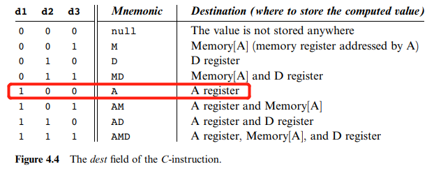
所以需要先用 Mux16 将 instruction 和 ALUout 多路复用,而在到达 ARegister 后,又出现了一个 control bit,此时为了将区分这两种情况的 bit 位组合起来,需要使用一个 Mux 来实现。
同时,观察到图示上 ARegister 的 output 也指向了 addressM,这也就是说 ARegister 与 Memory 是对应的,而我们已经知道了 Memory 的地址是 15 位的,所以 ARegister 的前 15 位就是 addressM。
综上,与 ARegister 相关的内容,可以设计为:1
2
3
4
5
6// instruction[15]: 0 -> A, 1 -> C
Mux16(a=instruction, b=ALUout, sel=instruction[15], out=uins);
// ARegister
Mux(a=true, b=instruction[5], sel=instruction[15], out=insA); // ALUout -> A Register
ARegister(in=uins, load=insA, out[0..14]=addressM, out=uAreg);
再接着朝右走,ARegister 的 output 会和 inM 一起进入 Mux16,也即:1
2// inM
Mux16(a=uAreg, b=inM, sel=ca, out=u1);
之所以这里会用到 Mux16,是因为只有 C 指令的 a bit 才能区分这条 C 指令是操作 M 寄存器的,反之就是 A 指令了。
DRegister and writeM
继续观察设计图,ALU 的输入一共有两个,已经解决了一个,还有一个 DRegister 需要解决。
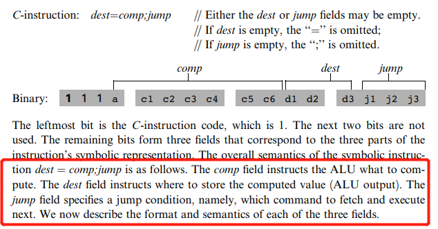
相比 ARegister 而言,DRegister 就简单多了,只有一个输入就是 ALU output,同样按照第四章的知识:
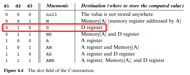
所以我们只需要讨论对应指令的 d2 位即可:1
2// DRegister
DRegister(in=ALUout, load=d2, out=uDreg);
同时,我们也可以发现只有当 d3 为 1 时,才会写入 M 寄存器,也就是 writeM 才会是 1:1
2// writeM
And(a=instruction[15], b=d3, out=writeM);
这里可能会有人疑问为什么是 C 指令的 d2 和 d3 位,实际上书的第四章已经解释了:
ALU
解决了 ALU 的输入问题,现在再考虑如何使用 ALU 来完成计算。
ALU 的接口直接参考书上的图示:
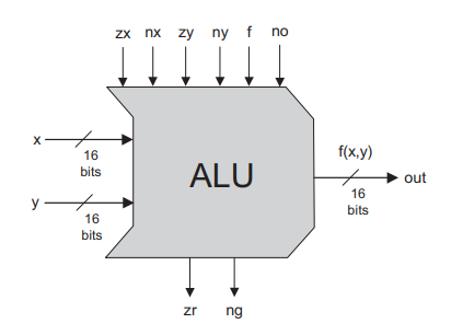
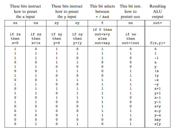
除了两个输入,还有 6 个控制位需要解决,而这 6 个控制位正好对应的就是 C 指令的 comp bits:
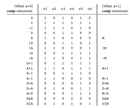
同时,从上面的指令图中也可以看出 ALU 的 x 一定是 DRegister 的输出,y 一定是 ARegister 的输出和 inM 中的一个,比如下面这条指令:
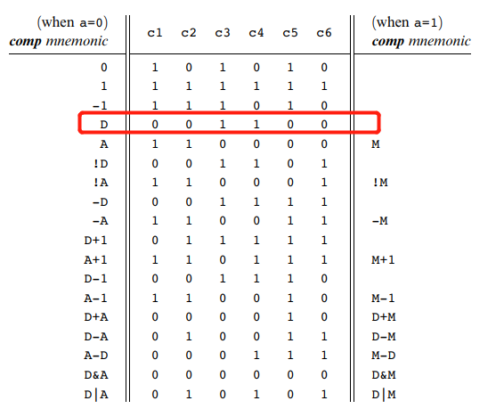
所以 ALU 可以设计为:1
2// ALU
ALU(x=uDreg, y=u1, zx=c1, nx=c2, zy=c3, ny=c4, f=c5, no=c6, out=ALUout, out=outM, zr=zr, ng=ng);
C-JUMP by PC
最后要实现的功能是 C 指令的跳转功能,这部分功能是通过 PC 来实现的,但是否跳转取决于 C 指令的 jump field:
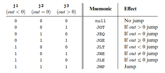
根据 ALU 输出的 zr 和 ng 刚好可以判断 output 的大小:1
2
3
4
5
6
7// PC
Not(in=zr, out=notzr);
Not(in=ng, out=notng);
And(a=notzr, b=ng, out=negative); // ALUout < 0
And(a=zr, b=notng, out=zero); // ALUout = 0
And(a=notzr, b=notng, out=positive); // ALUout > 0
接下来,再来逐一实现跳转功能:1
2
3
4
5
6
7
8
9
10// JUMP
And(a=j3, b=positive, out=JGT); // JGT
And(a=j2, b=zero, out=JEQ); // JEQ
And(a=j1, b=negative, out=JLT); // JLT
And(a=j1, b=j2, out=tmp);
And(a=tmp, b=j3, out=JMP); // JMP + JNE + null
Or(a=JGT, b=JEQ, out=jmp1); // JGT + JEQ + JGE, 3 possibilities
Or(a=jmp1, b=JLT, out=jmp2); // jmp1 + JLT + JLE, 5 possibilities
Or(a=jmp2, b=JMP, out=jmp3); // jmp2 + JMP + JNE + null, 8 possibilities
考虑到 PC 还有一个自增的功能,当指令为 A 指令时,不进行跳转,PC 自增:1
2And(a=instruction[15], b=jmp3, out=load); // not C-ins
Not(in=load, out=inc); // increment
最后写入 PC 中:1
PC(in=uAreg, inc=inc, load=load, reset=reset, out[0..14]=pc);
CPU_Codes
1 | // This file is part of www.nand2tetris.org |
Computer
Computer 的设计思路还是参考老师上课给出的思路:
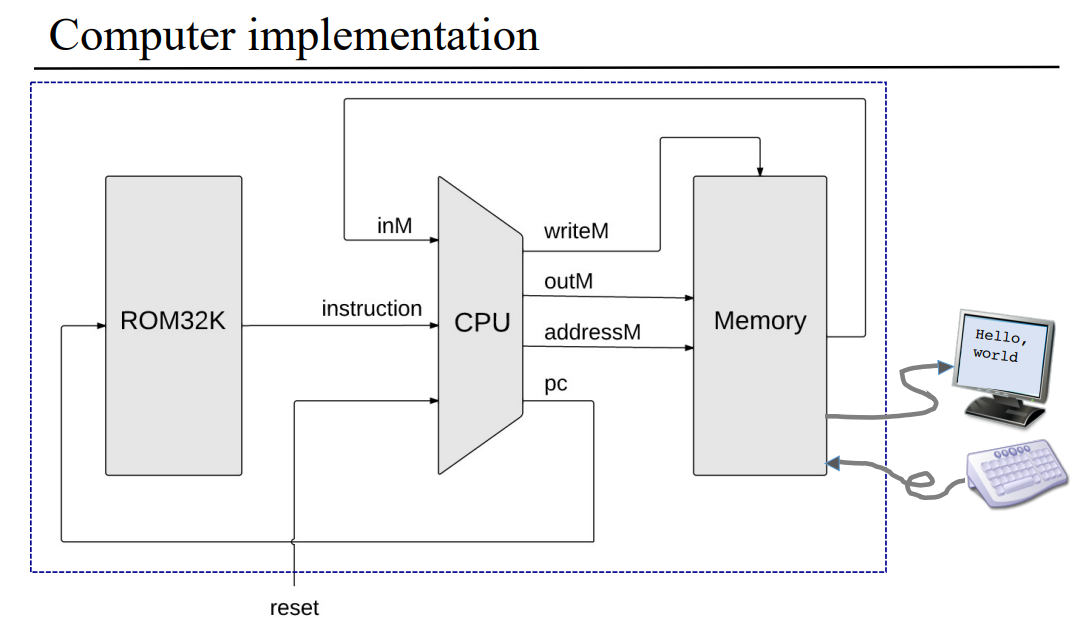
有了前面的设计基础(被反复拷打🤣),现在只需要按照上图中的思路将各个硬件连接起来即可,最后得到的代码如下:1
2
3
4
5
6
7
8
9
10
11
12
13
14
15
16
17
18
19
20
21
22
23
24
25
26
27// This file is part of www.nand2tetris.org
// and the book "The Elements of Computing Systems"
// by Nisan and Schocken, MIT Press.
// File name: projects/05/Computer.hdl
/**
* The HACK computer, including CPU, ROM and RAM.
* When reset is 0, the program stored in the computer's ROM executes.
* When reset is 1, the execution of the program restarts.
* Thus, to start a program's execution, reset must be pushed "up" (1)
* and "down" (0). From this point onward the user is at the mercy of
* the software. In particular, depending on the program's code, the
* screen may show some output and the user may be able to interact
* with the computer via the keyboard.
*/
CHIP Computer {
IN reset;
PARTS:
// Put your code here:
ROM32K(address=Upc, out=ROMins);
CPU(inM=MinM, instruction=ROMins, reset=reset,
outM=UoutM, writeM=UwriteM, addressM=UaddrM, pc=Upc);
Memory(in=UoutM, load=UwriteM, address=UaddrM, out=MinM);
}
Unit 5.6 Perspective
这周一共只有两个问题:
- 冯诺依曼结构和哈佛结构有什么差异?
- 哈佛结构是冯诺依曼结构的一个变种,二者的差异在于哈佛结构的数据内存和指令内存是分开的,而冯诺依曼结构的数据和指令是存放在一起的,这也就导致哈佛结构进行取址执行只需要一个时间周期,而冯诺依曼结构需要两个独立的时间周期。另外,还提到了如何构建结合两种结构特点的计算机,答案就是通过有限状态机的形式来构建,这里不深究。
- 计算机连接其他的外设,是如何工作的?
- 除了键盘和屏幕,计算机有很多其他的外设(这里的外设包括显卡、网卡等硬件设备),而计算机连接这些外设的方式与连接键盘和屏幕是类似的(注意这里的类似指的是现代计算机而不是 Hack)。换句话说,现代计算机连接外设都是通过设备控制器(device controllers)来完成的,这点其实也可以从 Windows 系统中的设备管理器页面看出,而之所以要这样做是为了降低 CPU 的工作压力。
Unit 5.7 Summary
这一章真的让我感慨良多...(其实是被虐的体无完肤🤣,不过还是完成了😤)
本章算是对前五章内容的汇总,基本把前五章所学的知识点都概括进来了。一开始琢磨 CPU 和 Memory 如何设计的时候,真的是脑袋都要想破了,想了很久一点头绪都没有,导致自己越想越烦躁,越想越想不出来,完全冷静不下来。然后,就一直拖着,结果就是进度很慢,花了半个月,这篇 Blog 才完成...这样真的不好😥,还是要注意效率。
现在回想起来,不够冷静是一个问题,还有一个问题是自己完成这些内容的时间间隔太长了,第一章的基础芯片、第二章的 ALU 和第三周的 RAM,都是一两年前完成的了,现在重新捡起来学习,原来的感觉都没了...
所以,学习需要趁热打铁,熟练才能生巧!
另外,还想说的是,前五章的核心内容就是如何设计硬件,而贯穿前五章设计硬件的技巧(或者说思路),就是如何使用特定的 control bit 来分情况输入输出比特流,这一点在 Mux、ALU、RAM、PC、CPU 和 Memory 上都有体现。
最后,希望自己再接再厉,趁热打铁,赶紧把第六章的汇编器完成了,这回不能偷懒了!😤

